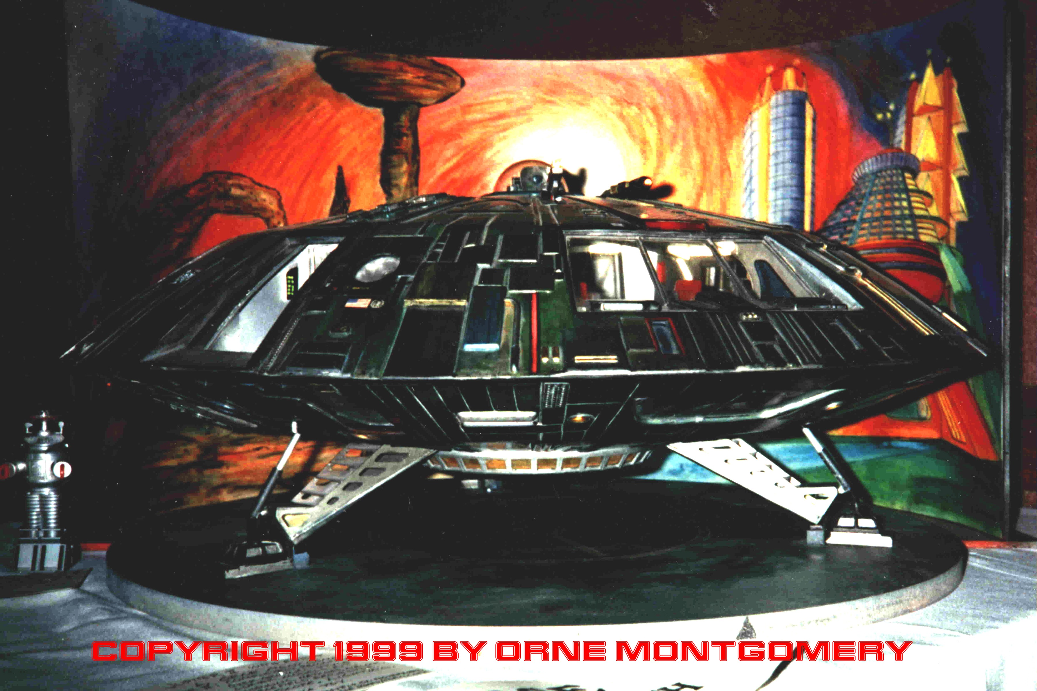
Las Vegas artist Eric Montgomery has returned with this fantastic and original build of the Jupiter II!! I love this!

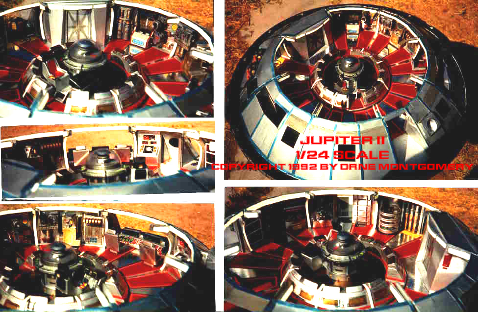
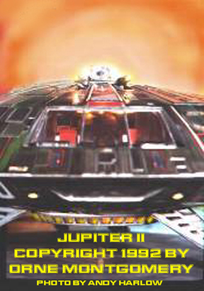
JUPITER II
1/24 scale
by Orne Montgomery
Construction and 2011-dated photos by Orne Montgomery. All other photos by Andy Harlow.
“It’s Back….and It’s Not What You Expected!”
Coincidentally with the release of Lunar Models’ 1/24 scale Jupiter II kit in 1991 (half-scale to the prototype), the publication of Innovation Comics’ illustrated revival of
the ‘Lost in Space’ TV-series was announced in Starlog Magazine (July I99l, #168). The article was accompanied by several artist-renderings of a radically modified Jupiter II. As I already had one of the new kits on order from Lunar Models, the decision was reached to make over the model to resemble the updated spaceship. (In the comic, as seen through Penny Robinson’s “diary”, the Jupiter II that was viewed on TV – as well as the Robinsons’ adventures – were her fanciful daydreams of reality; otherwise (with additional repairs made during eight long years of star-travel), this was the Jupiter II’s true appearance.
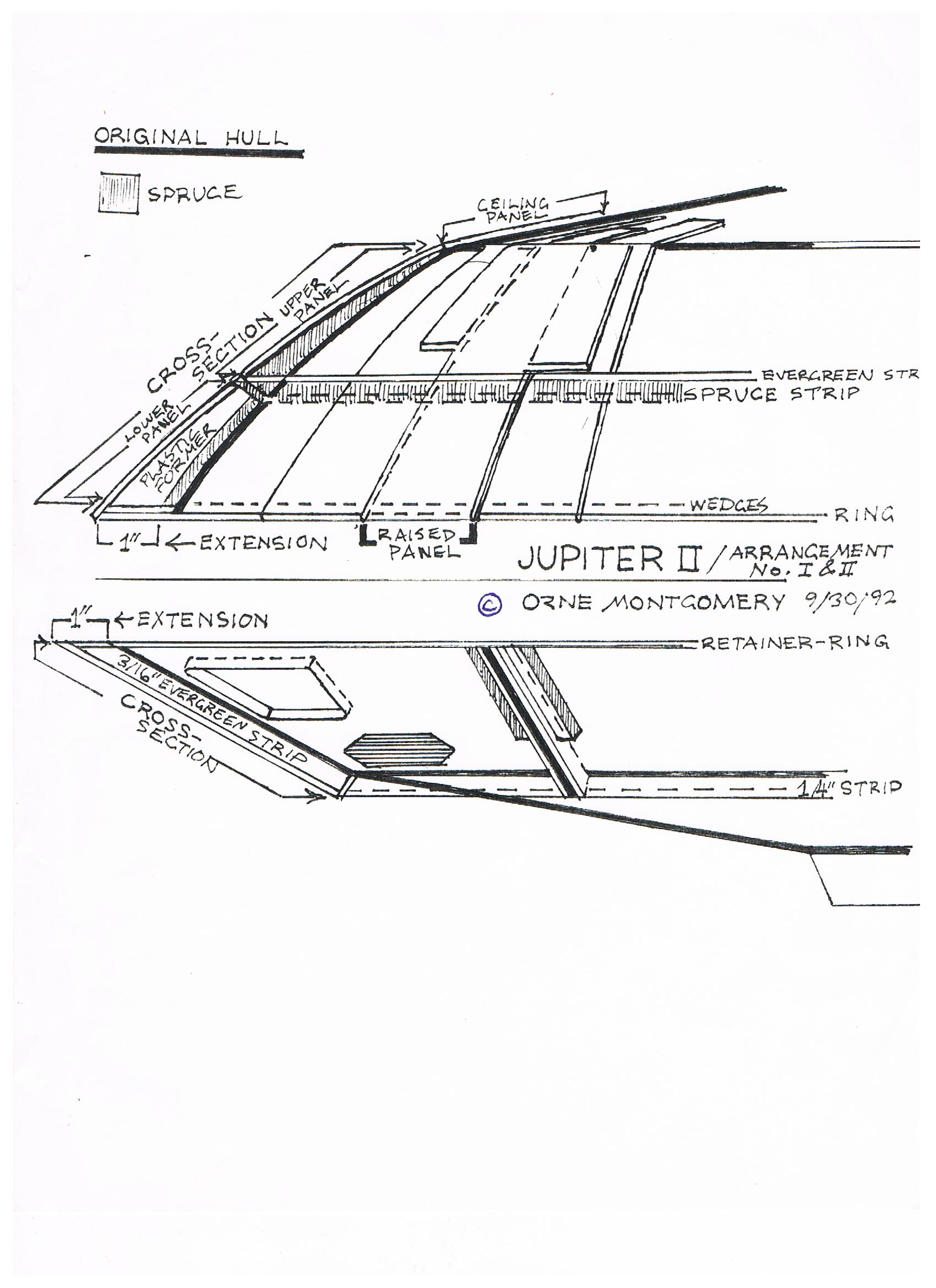
Unfortunately, the artists’ renderings were far from complete on specific details, or even plan-views, and I was left with the task of extrapolating all other facets of the design from scratch. Unlike my usual practice, I didn’t draw up any plans for the modifications (the cross-section arrangement was done later as contest-documentation) and, immediately upon receiving the model, I began construction over the Lunar Models kit. (The kit itself included clear vacform pieces for the dome-bubble and fusion-core insert; and cast resin pieces for the fusion-core, flightdeck window-frame, control-console blanks, and the landing-gear casings.)
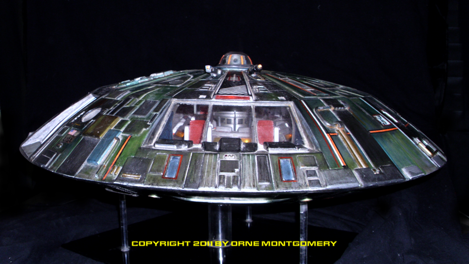
The kit’s basic structure was first altered by adding an inner retainer-ring, cut from a sheet of Lexan plastic, and an extension ring cut from sheet styrene plastic, onto the Lower Hull. This combined ring, extending the hull-diameter from 24″ to 26″, allowed the outer perimeter of the Upper Hull to be raked far more sharply toward the rim, as depicted in the illustrations; with the addition of spruce friction-rings around the rims of both hulls, the retainer-ring would also hold the
Flightdeck interior in place. No lower decks (crews-quarters and fusion-core) were built, as none could possibly be fitted into the original studio models the kit is based upon. (Theoretically, the dimensions of the Jupiter II would need to be enlarged from 18’x 48′ to 3O’x 80′ – gear retracted – to encompass all decks and bays seen in the series.) The Lunar kit had hefty gauge hull-halves, which allowed modification without a great reliance on interior-formers; only small triangular ribs were required around the edge of the retainer-ring.
Plans for the 1/35 scale Jupiter II were obtained from Lunar and the retractable landing gear templates were enlarged 33%. Operable retract-struts were made from aluminum tubing, with brass tube and piano-wire inserted into the T-bars; the
lower stalks are flexible drinking straws with rubber cores cut from a screen-door liner. Three landing-gear bays were constructed per the plans and the finished struts
and casings dropped in. #64 rubber-bands were attached to the T-struts, then epoxied in place – through the center bulkheads – with nylon washers. Styrene plate anchors
were used to keep in place the nylon-cloth casing-hinges.
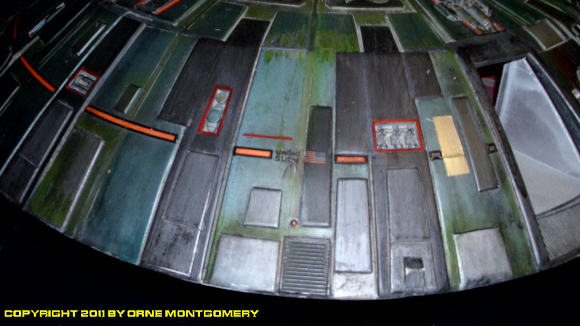
The outer ring of the hull was elevated one-quarter inch from the surface, to provide the recessed area surrounding the central fusion-core/landing gear section, with plastic support-beams – aligned toward the center – were glued around the
rim in intervals. Eight 46X pie-section panels were cut from Sintra plastic, which can be curled and bent more readily than styrene, simply by rubbing a piece between yourfingers and letting friction-heat do the rest, and curved to shape over the outer ring. Prior to being glued in place over the support strips, all cut-outs for recessed panels were opened, then boxed with sidewalls, and panels/detail-parts added. (Mostly auto parts such as flatheads, carbs, and intake manifolds.)
The Flightdeck windowframe and working airlock-hatch (with its adjacent porthole, the latter was moved twenty degrees toward the windowframe to correspond with the original studio-floorplans) were fitted into the Upper Hull. A clear plastic bottle was welded into the dome-opening to provide illumination to the dome from the interior. The Upper Hull was then aligned with the Lower Hull retainer/extension-ring. Semi-circular plastic sections were glued in place around the rim to construct a duplicate extension-ring, overlaid with another series of magnetic strips. With the exception of the airlock area, joint-spacers with curved vertical formers of plastic were glued. Each ended at the “midway-mark” up the hull (shorter lengths
were used beneath the flightdeck windows). A doubled ring of spruce and plastic was cemented in place over the “midway
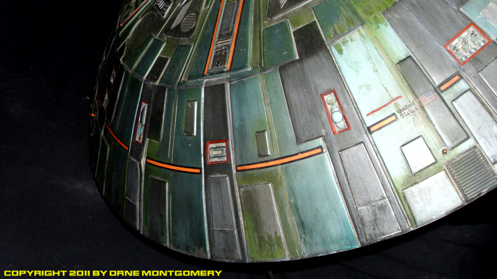
mark”, then double-walled panels of Sintra and styrene were laminated over the vertical formers. Shaved to a narrow angle – the wider part butted against the ring – vertical spruce
strips were added to the remaining upper half of the hull. Sintra sections were added to the upper-half of the hull; this provided the necessary radius which curves more sharply toward the “roof” from its “midway-mark”.
The Upper Hull was marked for extra paneling and cut-outs, and the remaining cavities were sealed with twelve full-height Sintra plate-sections, 22.5 degrees apart; these also had cut-outs with boxed sidewalls of styrene-strip, into
which were inserted detail-parts. Roof-panels – with inserts out from various styles of Evergreen roofing/railroad siding sheets, and additional placement of selected parts
from the spares-box – were edge-sanded, like all of the many raised panels on the model, to provide a “machined” appearence.
Temporarily remated to check alignment, the edges of the Upper and Lower Hulls were filed and sanded flush. Additional detail panels (some to conceal mating-bolts) were glued on with nylon-hinges; piping and other detail parts were then added to both hulls. Extension pieces were made for the landing-pads to fit the revised lower hull; Sintra plastic was used to make the Lower Hull collision-shields.
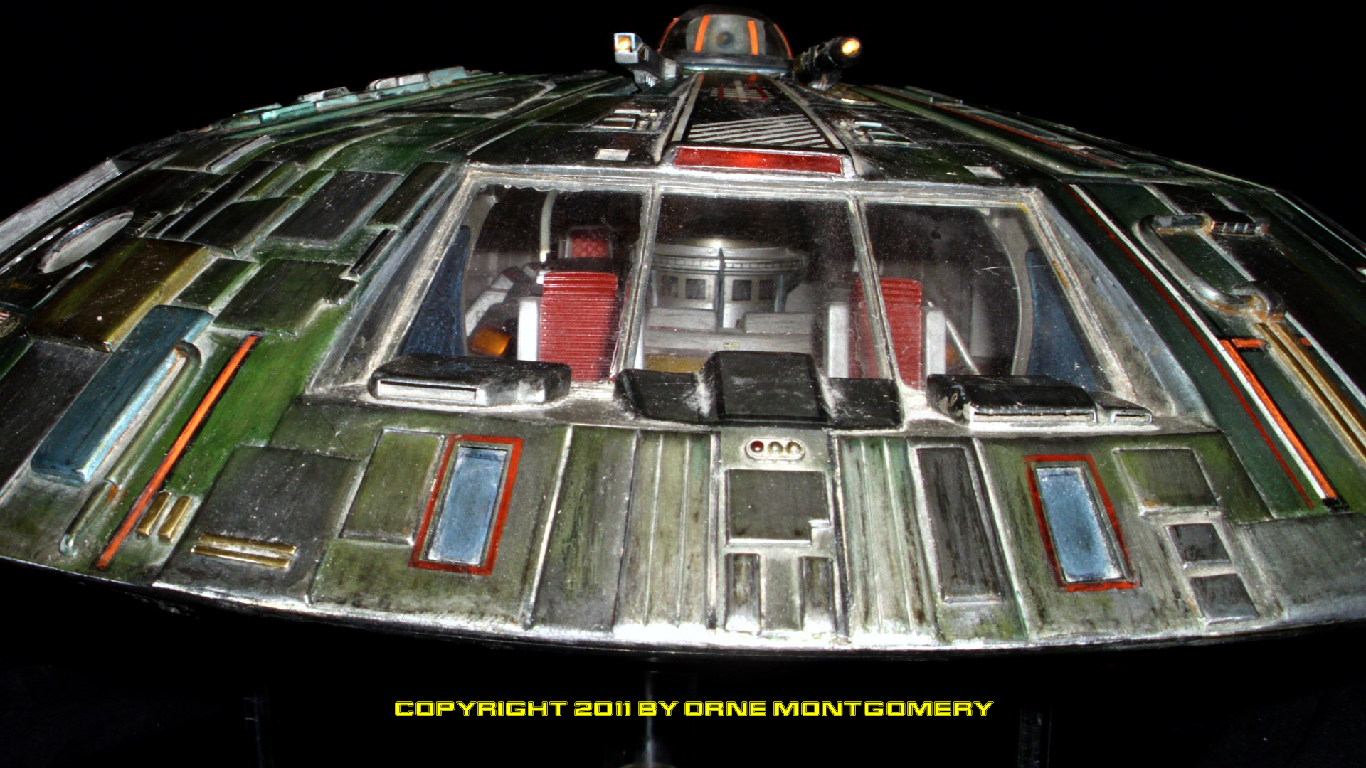
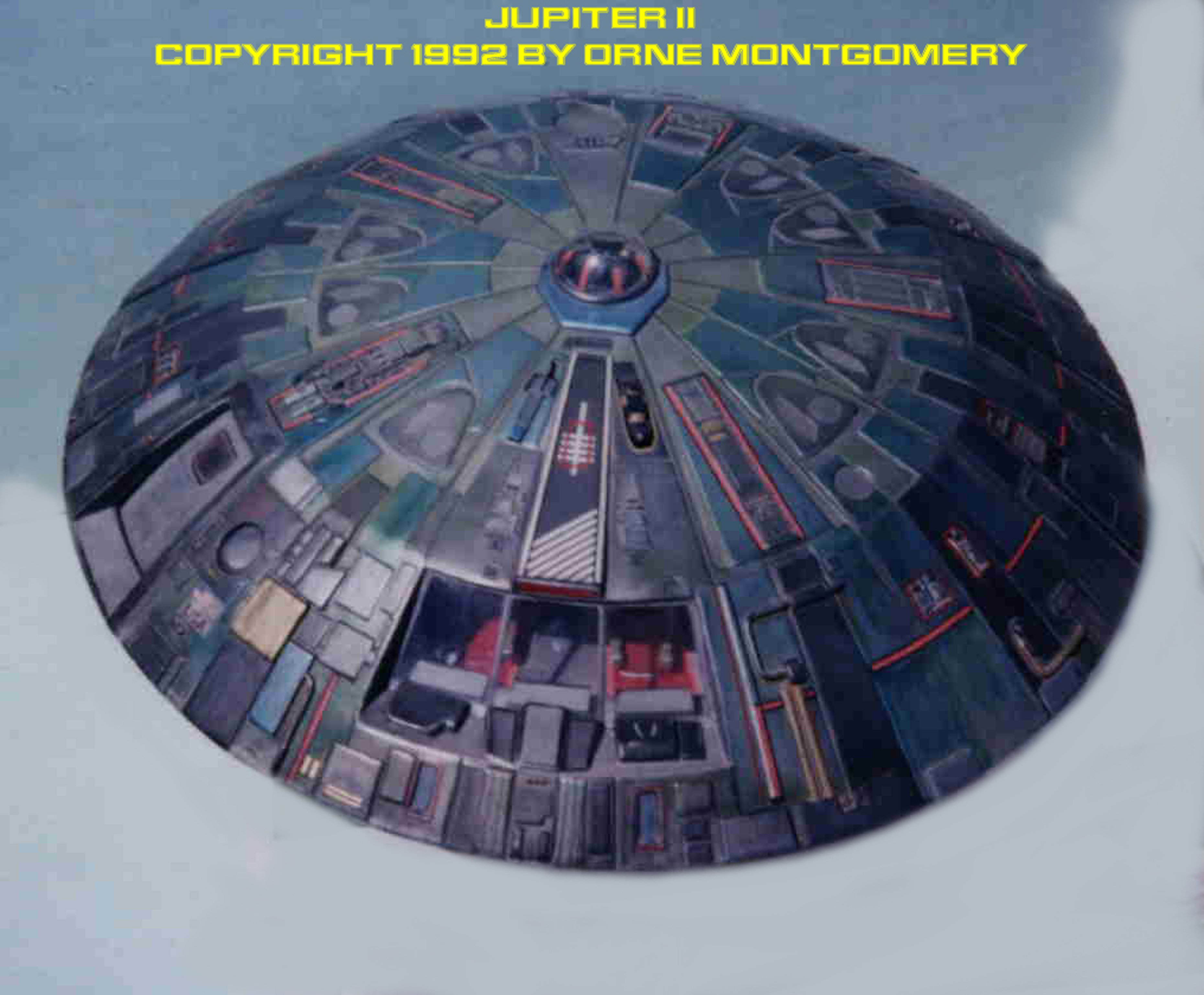
The Flightdeck retains the original eight-section
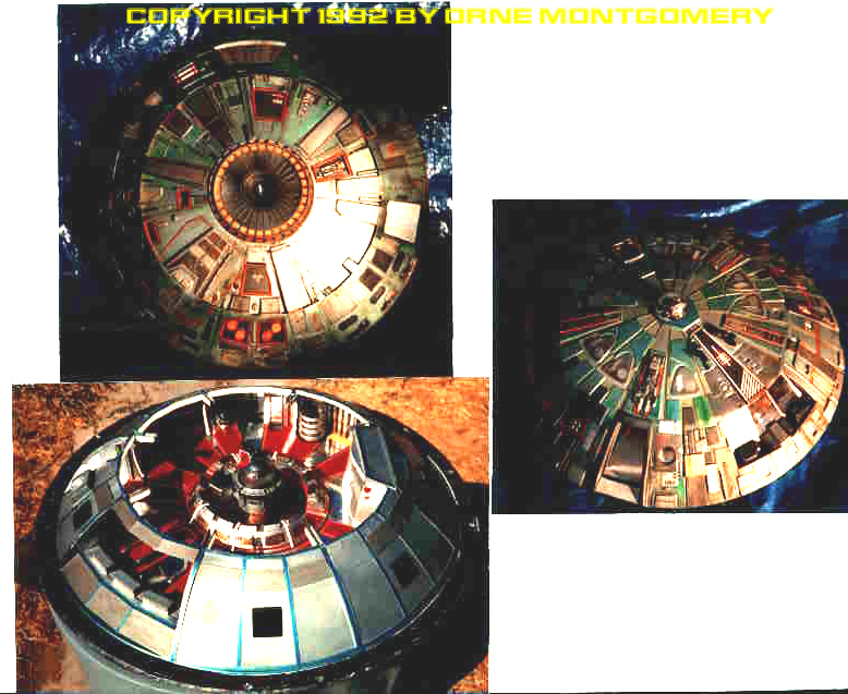
floorplan. Two double-walled cockpit arch-supports were traced from templates, and – as were the other six arches – fabricated from Sintra. Quarter-inch Evergreen stripswere glued along the inside curves of each arch. All eight flightdeck support-arches were glued onto the plexiglass disc – divided into 45-degree arcs – of the Flightdeck. The angled wall-spaces between each were measured off the studio-plans; foam-core walls were hot-glued one-half inch back from where the actual interior walls would be placed. (This allowed the wall-assemblies to be painted and fitted last, and also provided room for wiring.) As the Freezing Tubes went unseen during the two final seasons of the TV-series, they were not included. (Not till later in the comic-book’s run were they used for one more special and long overdue purpose. Read “Postscript”. At this point, I went beyond the original concept of the comic-series design, deciding that the interior should reflect the functional exterior. It was altered accordingly; beginning with the kit’s resin consoles and the instruction-sheet templates.
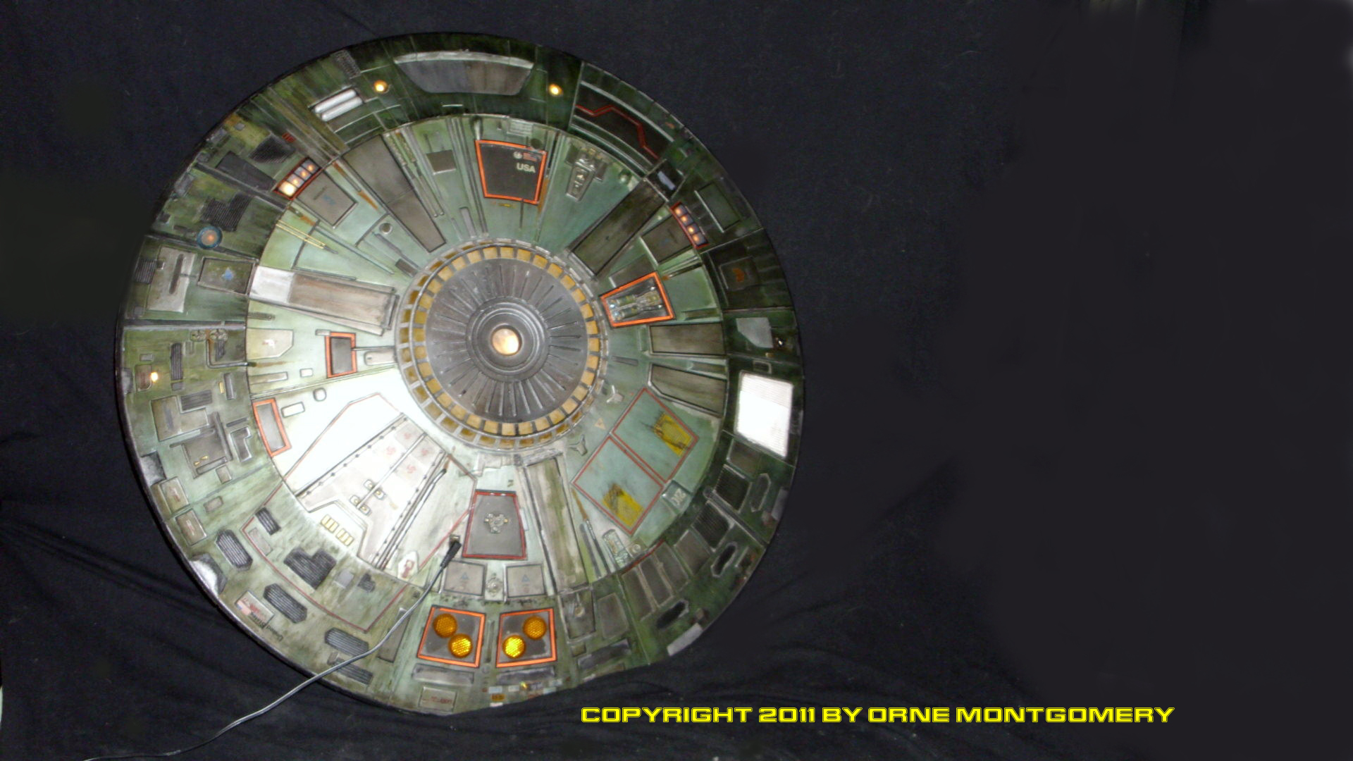
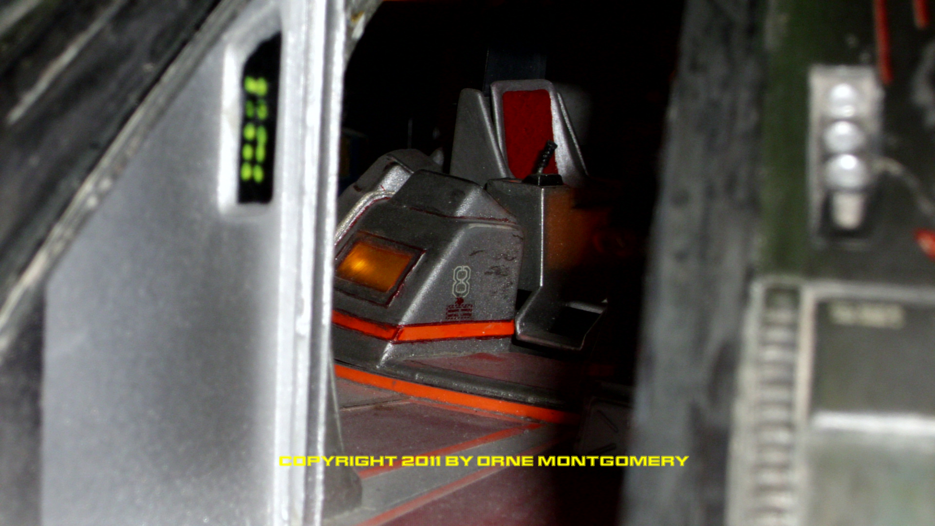
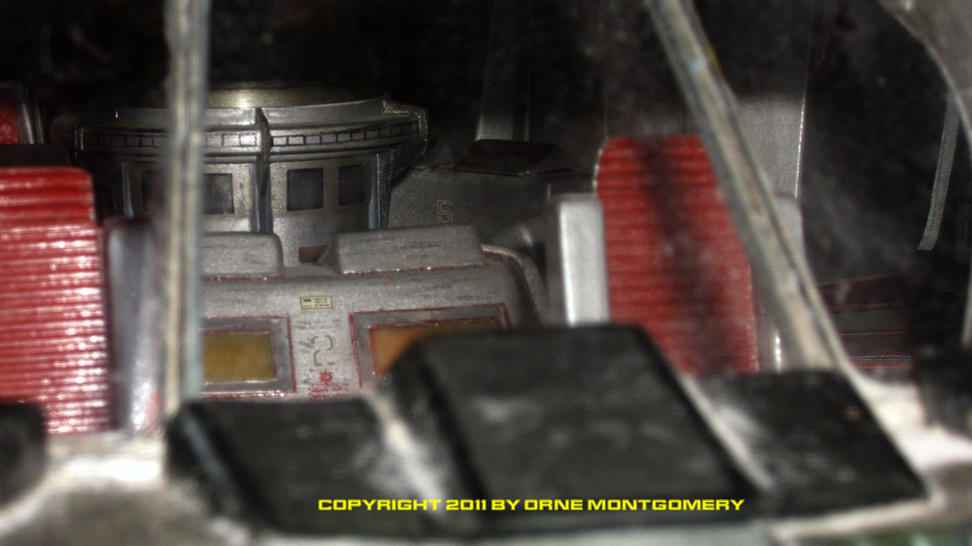
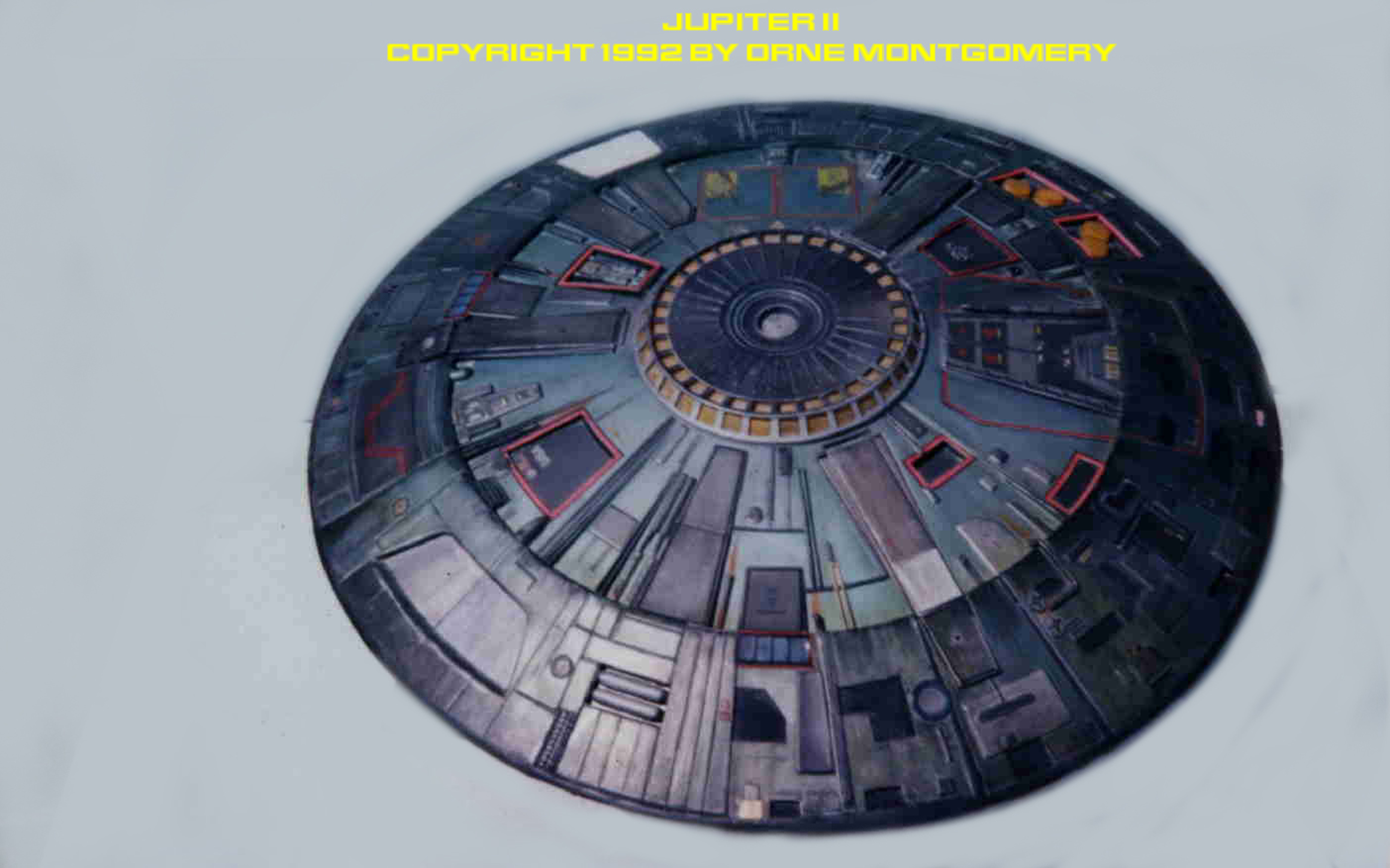
The cockpit area was built up with additional console-faces made from clear Butyrate, Sintra, and Evergreen. (Pilot-seats would be scratchbuilds.) The most prominent revision is the scratchbuilt circular module encompassing the astrogator (shown before final details added). Constructed in a fashion similar to the outer-ring extension of the Lower Hull, with detail added from the parts-box, this is a combination observatory and central computer with memory-core. Remember, the Jupiter II was an advanced colonization ship; given the violent circumstances surrounding its launch, it’d be inconcievable that no means of propagating a scientifically-advanced human settlement would be deleted from its equipment-roster. In other words, every bit of human knowledge would be sent along – recall the massive effort undertaken in both the novel and movie versions of ‘When Worlds Collide’, to ensure that this same knowledge survived the destruction of Earth. The remaining interior was assembled from kitbashed or scratchbuilt components. All console displays and controls were back-painted with translucent enamels and ink-detailing. The astrogator-dome is a second clear bubble provided by Lunar Models. Overhead wall-supports (with clear butyrate inserts for indicator panels and lighting fixtures) and ceiling support beams, were made from spruce, Sintra, and Evergreen “Odds’n’Ends”. These beams were connected to a core cut from a section of PVC pipe; a tube-insert was made through which a 7.2 volt bulb was added
for the main interior light. Ceiling panels and inner hull walls with removable hatches were constructed to conceal wiring. The dominant color of the Flightdeck is metallic silver, which brightened the recessed areas by reflecting the available light. The floor-covering is made from sections of red satin ribbon (backed with double-sided carpet tape) and Monokote
chrome trim-sheet, gold, red, and black trim-tape was used for detail All areas were oversprayed with clear acrylic enamel, then rubbed with medium-to-fine grade steel wool to “wear” the finish. 3-M ScotchLite was used for the”light” panels on the arch and overhead supports.
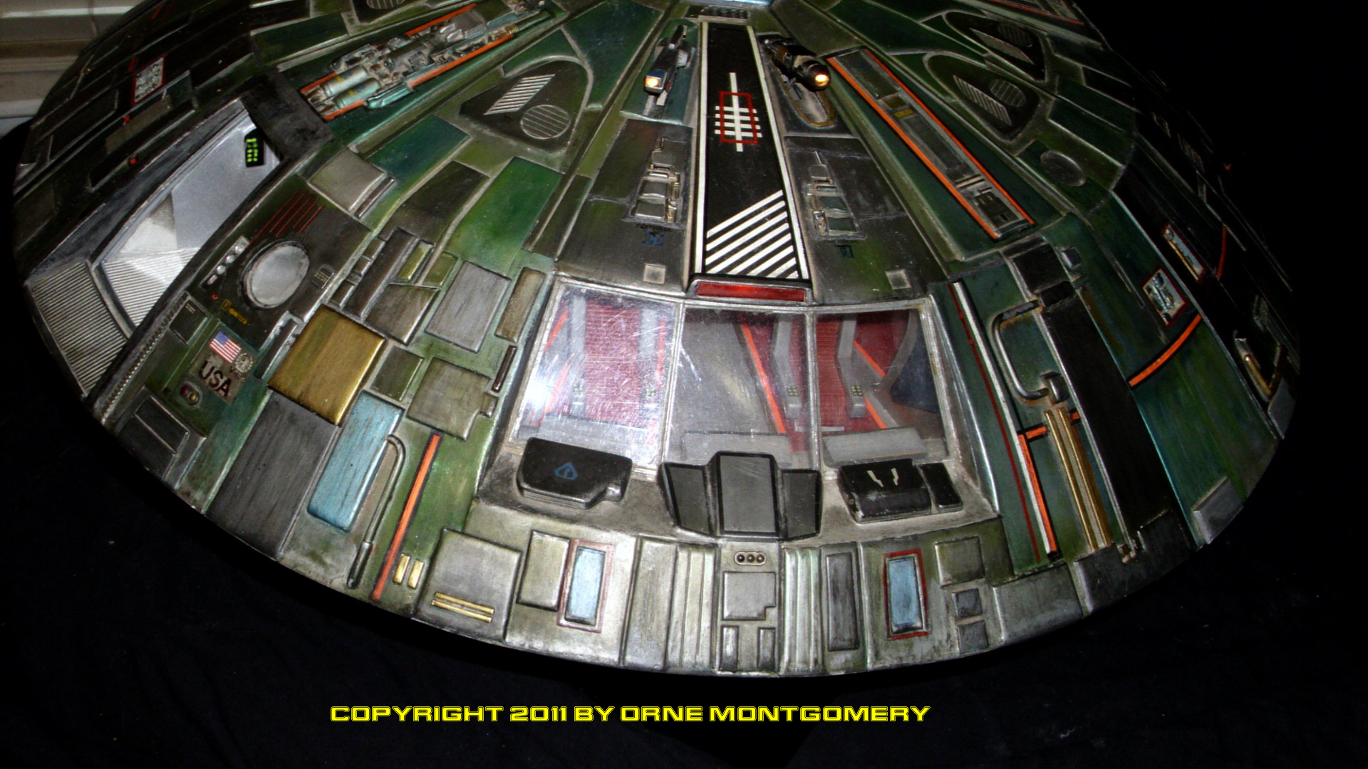
Flat black primer – to prevent interior-illumination from leaking through the finish – was sprayed inside the hulls, Krylon Primer Grey was applied to the exterior and buffed with medium steel-wool. An overall color of Testor’s Metallizer Stainless Steel was sprayed over the primer, then buffed; the finish was shot with Metalizer Sealer. Light coats of Polly S Anodized Metallic Blue and Interior Green, for shading, followed. “Mold-it” latex rubber was then brushed in alternating layers onto the exterior to mask all panel-work for different colors. Paints were primarily Testor’s Metallizers, airbrushed. Further detail was added with enamels and inks. Striping-tape and decals were laid on (the one set of decals most people won’t see is a batch of license plates attached to the lower aft rim by the “Alpha Control launch crew”) and several clear coats of acrylic were sprayed on to fix these in place. The first layer of weathering was laid down with dry-brushed enamels and rubbed-on chalk pastels. Testor’s Zinc Chromate was then applied to the hull in airbrushed “splatters”: in the comic-series, this “vegetable-shellac” serves as a protective ablative-coating. Another dusting of weathering with dry pastels, and three coats of clear acrylic enamel to seal everything, followed. All exterior sections were scrubbed with medium steel-wool to wear the completed finish.
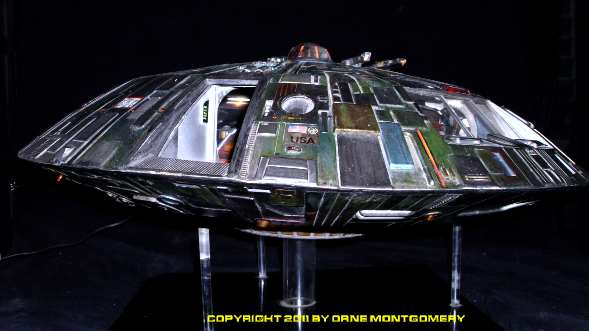
The sliding airlock-hatch is the original kit part (with clear butyrate portal), cut from the hull and placed on strip-runners built into it. An opening rear-hatch is mounted
in the lower hull to allow access to a toggle-switch for the lighting system. To either side of the “Cyclops-eye” panel above the Flightdeck windows are the observatory telescope and the shipborne force-field projector (the last device alluded to
in “The Derelict”); both are lighted and retract into their respective housings. There are approximately sixty-five working lights in the model; as the interior was an “on-the-run” affair and constantly being refitted for effect, plans to bundle fibre-optics into it were discarded and various size light-bulbs – wired in a “parallel” circuit, to insure the burnout of one bulb wouldn’t extinguish the entire network – were substituted. Two more 7.2 volt bulbs were used to light up the fusion-core (the advertised Lunar unit was unavailable during construction). All exterior/running lights were hooked up with gloved alligator-clips so that the model could be safely disassembled for refitting. Wire-soldering was done by Adam Stines, an R/C model car-builder; and the wiring-harness hook-ups were completed by Aaron Mach, an electronics-prop builder whom worked in the movie-industry. The power-source for all lighting is external; after several experiments with various units – including an internal 7.2 volt rechargeable flatpack-battery – a 340 watt
transformer was purchased (with a 7′ I.E.C. cord) from All Electronics Corp.; an AC/DC transformer jack is built into the hull beside the rear landing-gearcasing.
POSTSCRIPT (1993):
At the request of David Campitti, publisher of Innovation Comics, photos of my Jupiter II were supplied to the company in 1992 as source-material for their artists; these were
used to render the Jupiter II in the last cycle of issues for the series before publication was suspended when the company went out of business. (In issue #19, the lamentedly
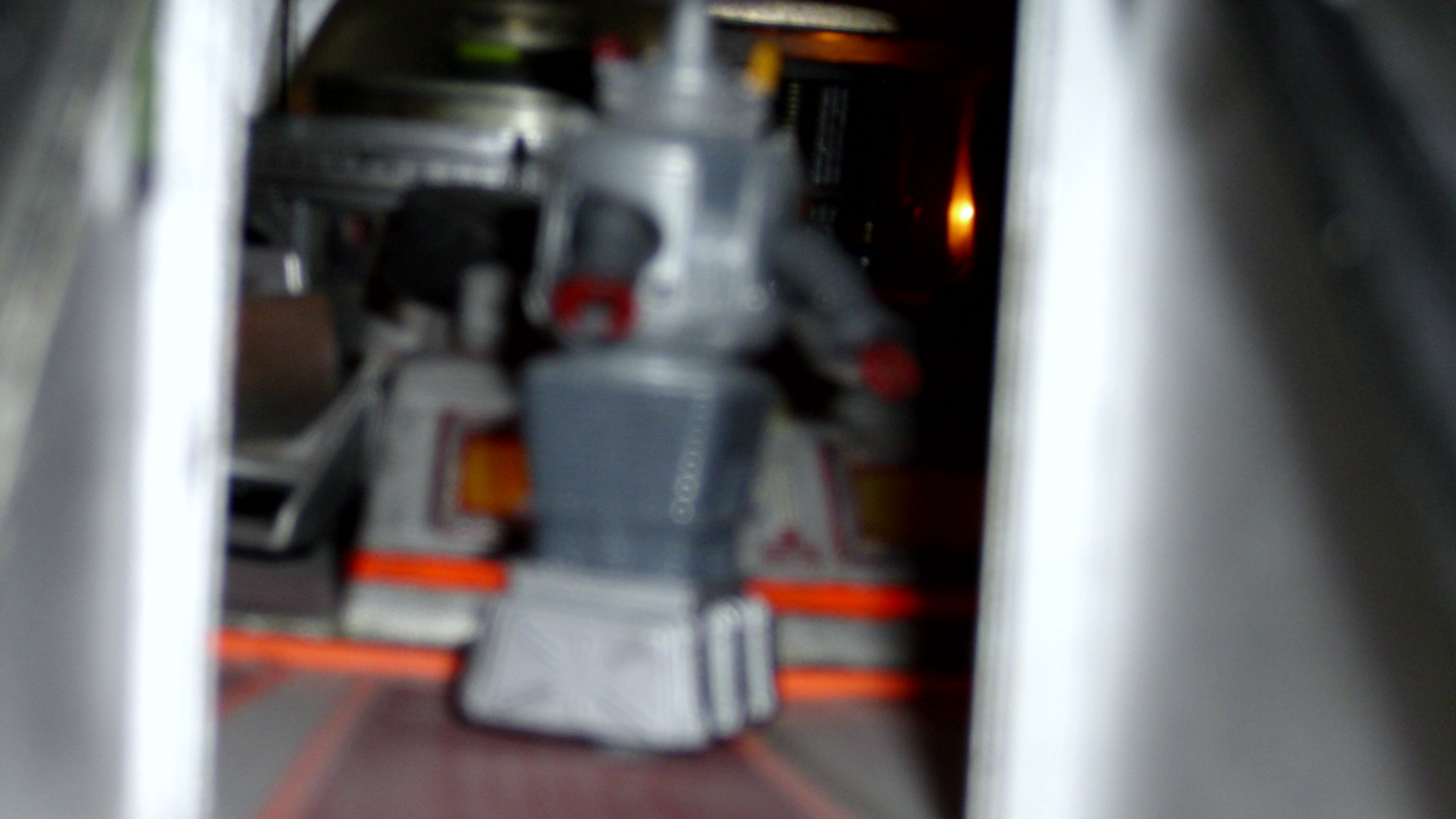
last published monthly story, the Robinsons and Co. – with Dr Smith FINALLY stuffed into a Freezing Tube – had arrived in the Alpha Centuri system, only to run afoul of the aliens whom had created the hyperdrive technology of the Jupiter II – back-engineered from a crashed scout ship piloted by the alien leader’s son. “…It’s not what you expect.”)
POSTSCRIPT (2012):
Mike Evans at Lunar Models was able to have the model recognized by license-holder Viacom as the “official” model for the LIS comic-series. After several false starts at turning the model into a production kit for the various owners of Lunar Models (including tearing the finished model apart to make silicone rubber molds over a Christmas weekend with the help of Aaron Mach, then completely refinishing the original to match it’s previous appearence), the project went on hold and remains so.
The comic-series itself, I learned much later after it too went out of print, completed the last of the stories in a graphic-novel titled “Voyage to the Bottom of the Soul”, written by Bill Mumy (2005).